Allen-Bradley 802T-HPE-J-A: Durable Push Button Module for Industrial Panels缩略图

Allen-Bradley 802T-HPE-J-A: Durable Push Button Module for Industrial Panels

Allen-Bradley 802T-HPE-J-A: Durable Push Button Module for Industrial Panels插图


Product Overview

The Allen-Bradley 802T-HPE-J-A​ is a robust, 22mm diameter, oil-tight and water-tight push button switch module designed for demanding industrial operator interface applications. Part of the comprehensive Allen-Bradley 802T family of industrial control devices, this specific model is an illuminated, momentary-contact push button assembly built to provide reliable manual control input in harsh environments. The Allen-Bradley 802T-HPE-J-A​ integrates a switch contact block, a colored (often red) illuminated operator (button), and a mounting bushing into a single, pre-assembled unit ready for panel installation. Its core function is to translate a human operator’s physical action—pressing the button—into a secure electrical signal to initiate or halt a machine function, such as a start command, cycle initiation, or reset, while providing clear visual status feedback through its integrated illumination.Engineered for durability, the 802T-HPE-J-A​ features a rugged thermoplastic or metal operator and a sealing mechanism that typically meets IP67 or similar ratings, protecting the internal electrical contacts from ingress of dust, oil, coolants, and water spray commonly found on factory floors. The “J” and “A” suffixes in the model number 802T-HPE-J-A​ specify critical attributes: the contact configuration (e.g., 1 Normally Open contact), the voltage/type of the illumination (e.g., 120V AC incandescent or LED), and the specific lens color (e.g., red). The module is designed for easy installation into a standard 22.5mm panel cutout using its integral locking ring, allowing for tool-less mounting and removal. The value of the Allen-Bradley 802T-HPE-J-A​ lies in its combination of operator interface clarity, environmental toughness, and electrical reliability, making it a go-to choice for machine builders and panel integrators who require a dependable, visible, and sealed manual control point on industrial equipment.

Technical Specifications

Parameter Name Parameter Value
Product Model 802T-HPE-J-A
Manufacturer Allen-Bradley (Rockwell Automation)
Product Series 802T Industrial Control Stations
Product Type 22mm Illuminated Push Button Switch Module
Operator Type Momentary Push Button (returns when released)
Operator Color Typically Red (specific to the “A” suffix)
Lens Material Polycarbonate, high-impact
Illumination Integrated lamp (Incandescent or LED, voltage specific)
Contact Block Integral, 1 Normally Open (1NO) contact (configuration specific to “J”)
Contact Rating Typically 10A @ 600V AC or 5A @ 600V AC (resistive)
Electrical Life Hundreds of thousands of operations
Enclosure Rating IP67 (Dust tight and protected against immersion)
Mounting 22.5mm round panel cutout, with snap-in bushing
Operating Temperature -25°C to +70°C (dependent on lamp type)
Agency Approvals UL Listed, cULus, CE


Main Features and Advantages

The Allen-Bradley 802T-HPE-J-A​ is distinguished by its rugged construction and integrated, status-driven design. Its primary advantage is the sealed, oil-tight assembly that safeguards the switching mechanism from harsh industrial contaminants, ensuring reliable electrical performance and long operational life even in dirty, wet, or washdown environments. The operator is designed for high mechanical durability, capable of withstanding millions of actuations. The integrated illumination provides immediate and clear visual feedback to the operator; the red lens, when lit, can indicate that the machine is in a ready state, that the button’s function is active, or simply serve as a highly visible location marker in a large control panel.Ease of installation and maintenance are key benefits. The 802T-HPE-J-A​ is a factory-assembled unit, eliminating the need to separately order and assemble a contact block, lamp, and operator. It installs quickly into a panel with a simple push and a twist of the mounting bushing, significantly reducing panel build time. The lamp (or LED module) is typically replaceable from the front of the panel without needing to remove the entire switch or access the rear wiring, minimizing maintenance downtime. The clear, industry-standard 22mm form factor ensures compatibility with a wide range of panel cutout tools and accessory rings or guards. The combination of environmental sealing, robust switching elements, integrated status indication, and service-friendly design makes the Allen-Bradley 802T-HPE-J-A​ a reliable and cost-effective solution for adding durable operator control points to industrial machinery.

Emerson 800XP-SM32 Module: Standard Mounting Safety Logic Solver缩略图

Emerson 800XP-SM32 Module: Standard Mounting Safety Logic Solver

Emerson 800XP-SM32 Module: Standard Mounting Safety Logic Solver插图


Product Overview

The Emerson 800XP-SM32​ in Standard Orientation is a high-integrity, triple modular redundant (TMR) I/O and logic solver module that forms a core component of the DeltaV SIS (Safety Instrumented System) platform. This specialized module is engineered for the most demanding safety applications in process industries, where failure is not an option. The primary function of the 800XP-SM32 Standard Orientation​ module is to execute safety logic and interface with field devices to implement Safety Instrumented Functions (SIFs) that protect personnel, equipment, and the environment. It achieves this through a sophisticated TMR architecture, where three independent, synchronized processor channels simultaneously execute the same application logic and vote on the outputs. This design ensures that a single fault in any one channel does not cause a dangerous failure of the safety function, providing both high availability (to avoid nuisance trips) and high safety integrity.As part of the Emerson DeltaV SIS family, the 800XP-SM32​ is designed for seamless integration with the DeltaV distributed control system (DCS) while maintaining the physical and logical separation required for safety systems. Its “Standard Orientation” designation typically refers to its standard mounting and connection configuration within the 800XP series chassis, as opposed to a “Reverse Orientation” variant. The module’s value lies in its certified performance for Safety Integrity Level (SIL) 3 applications as per IEC 61508 and IEC 61511 standards. It provides 32 digital I/O points (configurable as inputs or outputs) in a TMR configuration, meaning each field signal is read or controlled by three independent circuits. The module handles logic solving internally, capable of implementing complex interlock, voting, and shutdown logic without relying on an external controller. The Emerson 800XP-SM32 Standard Orientation​ module is a critical element for implementing reliable emergency shutdown (ESD), fire and gas (F&G), and burner management systems (BMS) in hazardous processes.

Technical Specifications

Parameter Name Parameter Value
Product Model 800XP-SM32 (Standard Orientation)
Manufacturer Emerson Process Management
Product Type Triple Modular Redundant (TMR) Safety Logic Solver & I/O Module
Safety Certification SIL 3 (IEC 61508 / IEC 61511)
Architecture 1oo2D (One-out-of-Two with Diagnostics) or TMR, user-selectable per point
I/O Type 32 points, Digital, Configurable as Input or Output (Sink or Source)
I/O Isolation Grouped (points are isolated in groups, e.g., 8 points per common)
On-board Logic Solver Yes, capable of executing safety application logic
Diagnostic Coverage High (>99%), with extensive online diagnostics
Communication Integral to the DeltaV SIS bus for communication with other SIS modules and the DeltaV DCS
MTTFd (Mean Time to Dangerous Failure) Very High (>100 years typical)
Operating Temperature -40°C to 70°C (-40°F to 158°F)
Housing/Chassis Modules into the Emerson 800XP Series Chassis
Power Supply Powered from the 800XP chassis (typically 24V DC)
Status Indication Comprehensive LEDs for channel status, I/O status, and module health


Main Features and Advantages

The defining feature of the Emerson 800XP-SM32 (Standard Orientation)​ is its fault-tolerant Triple Modular Redundant (TMR) design. This architecture provides an exceptional level of safety and availability. The three isolated channels operate in lockstep, with a hardware voter comparing their outputs. If one channel disagrees due to a fault, it is automatically out-voted by the other two, and the system continues to operate correctly while diagnosing the faulty channel. This allows for online maintenance and repair without taking the safety system offline. The module’s high diagnostic coverage continuously tests the processors, memory, and I/O circuits, detecting over 99% of dangerous failures. This diagnostic capability is crucial for achieving and maintaining the SIL 3 rating, as it ensures failures are detected before they can compromise the safety function.

Accessory for 800F-PB: Allen-Bradley 800X-ALP Custom Legend Plate缩略图

Accessory for 800F-PB: Allen-Bradley 800X-ALP Custom Legend Plate

Accessory for 800F-PB: Allen-Bradley 800X-ALP Custom Legend Plate插图


Product Overview

The Allen-Bradley 800X-ALP​ is a specialized accessory kit designed to provide clear, professional, and customizable labeling for 800F series 22mm pushbutton operators, specifically compatible with models like the 800F-PB22MM. This accessory is an integral part of building a well-organized and user-friendly human-machine interface (HMI) on control panels, machinery, and operator stations. The 800X-ALP​ kit typically includes a durable, transparent legend plate and a set of inserts that can be custom-engraved with text, symbols, or icons to indicate the specific function of the pushbutton, such as “START,” “STOP,” “RESET,” “JOG,” or machine-specific identifiers. The primary purpose of this accessory is to enhance operational safety, efficiency, and accuracy by eliminating guesswork for operators and maintenance personnel, ensuring that every control device is unambiguously identified according to its role in the machine or process.As part of Rockwell Automation’s comprehensive 800F line of pushbutton and signaling devices, the 800X-ALP​ legend plate kit follows a modular design philosophy. It is engineered to snap or mount securely onto the front of the 22mm pushbutton operator, seamlessly integrating with the device’s aesthetic and functional design. The kit transforms a generic pushbutton into a clearly marked, application-specific control point. The value of the Allen-Bradley 800X-ALP​ lies in its ability to provide a standardized, professional, and durable labeling solution that meets industrial safety standards (like those requiring clear identification of emergency stop and other critical functions) and improves overall panel clarity. In complex control panels with dozens of buttons, proper labeling facilitated by the 800X-ALP​ is not just a convenience; it is a critical component for preventing operator error, speeding up troubleshooting, and ensuring compliance with good manufacturing practices and safety regulations. It represents the finishing touch that bridges the gap between electrical functionality and human usability.

Technical Specifications

Parameter Name Parameter Value
Accessory Model 800X-ALP
Manufacturer Allen-Bradley (Rockwell Automation)
Compatible Device Series 800F Series Pushbuttons, Selector Switches, etc.
Target Device Size 22mm Mounting (Specifically for operators like 800F-PB22MM)
Accessory Type Legend Plate Kit
Kit Components Typically includes a clear, protective legend plate frame and one or more blank inserts for engraving.
Insert Material Durable plastic (e.g., polyester) suitable for laser or mechanical engraving.
Plate Color/Finish Clear, transparent cover to protect the engraved insert.
Mounting Method Snap-on or slide-in attachment to the compatible 800F operator bezel.
Environmental Rating Matches the IP rating of the host operator when installed (e.g., IP65)
Customization Inserts are designed to be user-engraved with specific legends.
Primary Function To provide a protected, clear display of a custom legend for device identification.


Main Features and Advantages

The Allen-Bradley 800X-ALP​ legend plate kit offers a simple yet highly effective solution for panel identification with several key advantages. Its foremost feature is the provision of a protected, professional labeling surface. The two-part design—a clear, rugged outer cover and a replaceable inner insert—ensures that the custom engraving is shielded from abrasion, chemicals, UV light, and general wear, maintaining legibility over the long service life of the equipment. This protection is crucial in industrial environments where controls are subject to frequent use, cleaning, and exposure to oils or coolants. The kit enables complete customization; the blank inserts can be engraved in-house using standard engraving equipment or by a panel shop to create any necessary text, acronym, or standard symbol (e.g., IEC/ISO symbols for start, stop, emergency), allowing for precise communication in multiple languages or for specialized functions.Ease of installation and future modification are significant benefits. The 800X-ALP​ is designed for tool-less attachment, snapping securely onto the front of the compatible 800F operator. This allows for labels to be added or changed in the field without disassembling the pushbutton or its wiring, facilitating panel updates, machine repurposing, or correction of legends. The standardized kit ensures a consistent, clean appearance across the entire control panel, contributing to a professional and organized look. This consistency improves the operator’s ability to quickly scan and locate controls, reducing reaction time in normal and emergency situations. By using the Allen-Bradley 800X-ALP, system integrators and panel builders can deliver a finished product that not only functions reliably but also provides an exceptional level of operational clarity and safety, directly contributing to reduced human error and enhanced overall equipment effectiveness (OEE).

Honeywell 621-2200RC Relay Output Module for Fire and Gas Control缩略图

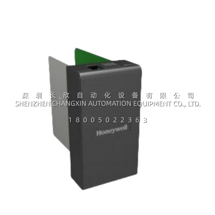
Honeywell 621-2200RC Relay Output Module for Fire and Gas Control

Honeywell 621-2200RC Relay Output Module for Fire and Gas Control插图


Product Overview

The Honeywell 621-2200RC​ is a robust, high-voltage relay output module designed for integration within Honeywell’s specialized safety and combustion control systems, such as those used in burner management (BMS), fire and gas (F&G) detection, and emergency shutdown (ESD) applications. This module functions as a critical final control interface, converting the low-voltage logic-level signals from a safety-rated controller into high-power switching commands capable of directly controlling field devices operating on 230V AC power. The Honeywell 621-2200RC​ typically incorporates electromechanical relay outputs, known for their ability to switch high inrush currents, provide complete electrical isolation between the control system and the load, and offer a physically visible “dry contact” that confirms the safety command has been executed. Its primary role is to reliably energize or de-energize critical safety actuators, such as fuel shut-off valves, ventilation dampers, alarm sirens, or shutdown solenoids, in response to commands from the safety logic solver.Engineered for mission-critical safety functions, the Honeywell 621-2200RC​ is built to the highest standards of reliability and failsafe operation. It is commonly part of certified safety instrumented systems (SIS) where its performance directly impacts the safety integrity level (SIL) of the safety loop. The module is designed with features that support safety principles, including clear status indication via LEDs, and is often used in redundant or voting configurations to enhance system availability and fault tolerance. The value of the Honeywell 621-2200RC​ lies in its ability to provide a robust, isolated, and highly reliable physical interface that ensures safety commands from the controller are faithfully and powerfully executed in the field, even in harsh industrial environments with significant electrical noise. It is a key component in safeguarding personnel, equipment, and facilities by ensuring that critical safety actions—like isolating a fuel source during a flame failure—are carried out with absolute certainty.

Technical Specifications

Parameter Name Parameter Value
Product Model 621-2200RC
Manufacturer Honeywell (often associated with Fireye, Honeywell Safety, or Honeywell Process Solutions)
Product Type Relay Output Module (230V AC)
Output Configuration Typically features Form C (SPDT – Single Pole Double Throw) relay contacts
Number of Channels Often 2 or 4 independent relay output channels (specific to variant)
Contact Rating 230V AC, with a specified current rating (e.g., 5A or 8A resistive)
Isolation Reinforced isolation between control side (logic) and load side (contacts)
Switching Type Electromechanical Relay
Status Indication LED per channel for output state (energized/de-energized) and likely a module health/fault LED
Input Control Signal Low-voltage DC signal from the controller logic (e.g., 24V DC)
Response Time Relay pick-up and drop-out time (tens of milliseconds)
Electrical Connections Screw-terminal or pluggable terminal block
Compatible System Honeywell Safety Controllers, Burner Management Systems (e.g., FS24, Flame Safeguard controls)
Safety Standards Designed to meet relevant industrial safety standards (e.g., for BMS per NFPA standards)
Operating Temperature Industrial temperature range (e.g., 0°C to 60°C)


Main Features and Advantages

The Honeywell 621-2200RC​ is distinguished by its use of high-capacity electromechanical relays, which provide intrinsic advantages for safety-critical switching. The relay contacts offer complete galvanic isolation, meaning there is no electrical connection between the sensitive control electronics and the high-voltage load circuit. This isolation protects the safety controller from voltage transients, surges, and faults originating in the field wiring. The “dry contact” nature of the relay provides a definitive, physically verifiable state, which is a fundamental requirement in many safety designs for proof testing. The high current rating of the contacts allows the module to directly switch substantial loads like motorized valve actuators or multiple alarm horns without requiring an interposing relay, simplifying cabinet design and reducing points of failure.Designed for safety and diagnostics: Reliability is paramount, and the Honeywell 621-2200RC​ is built with robust components suitable for long-term, maintenance-free operation in demanding environments. The module provides clear visual diagnostics through per-channel LEDs, allowing technicians to immediately confirm the commanded state of each output. Its design is tailored for integration into Honeywell’s safety architecture, ensuring compatibility and predictable performance within the safety loop. The module’s response is deterministic, providing a reliable and predictable delay between the control command and contact actuation. This combination of high-power switching capability, absolute isolation, clear status indication, and design integrity makes the Honeywell 621-2200RC​ a trusted interface for executing the most critical commands in industrial safety systems, where failure is not an option.

WAGO 750-628: Reliable Fieldbus Coupler for INTERBUS Protocol Integration缩略图

WAGO 750-628: Reliable Fieldbus Coupler for INTERBUS Protocol Integration

WAGO 750-628: Reliable Fieldbus Coupler for INTERBUS Protocol Integration插图Product Overview

The WAGO 750-628 Bus Extension Coupler Module​ is a specialized fieldbus interface unit within the versatile WAGO-I/O-SYSTEM, designed to function as a remote node on an INTERBUS network. This module serves as the critical communication gateway, connecting a local group of WAGO digital, analog, and special function I/O modules to a central INTERBUS master controller, such as a PLC. The primary role of the 750-628​ is to manage all data exchange between the connected field devices (sensors and actuators) and the higher-level control system over the high-speed, deterministic INTERBUS fieldbus. It acts as an intelligent interpreter, reading input data from the I/O modules, packaging it into the INTERBUS telegram, and receiving output commands from the master to write to the appropriate output channels. As a bus extension coupler, it allows for the creation of distributed I/O stations that can be located close to the machinery they control, significantly reducing long and costly field wiring runs back to the central control cabinet. The WAGO 750-628​ is renowned for its reliability and ease of configuration, automatically recognizing all connected I/O modules via its built-in microcontroller and assigning addresses accordingly. This plug-and-play functionality, combined with the mechanical robustness of the WAGO CAGE CLAMP® connection technology, makes the 750-628 Bus Extension Coupler​ a cornerstone for building flexible, scalable, and maintainable automation architectures in a wide range of industrial applications utilizing the INTERBUS protocol.

Technical Specifications

Parameter Name Parameter Value
Product Model 750-628
Manufacturer WAGO Kontakttechnik GmbH & Co. KG
Product Type Fieldbus Coupler / Bus Extension Coupler
Fieldbus System INTERBUS
I/O-SYSTEM WAGO-I/O-SYSTEM 750 Series
Data Transfer Rate 500 kbit/s (standard INTERBUS speed)
Number of Connected Modules Up to 64 I/O modules (limited by overall process image size)
Address Assignment Automatic via K-bus (WAGO’s internal bus)
Internal Supply Provides 5V DC to connected I/O modules via the backplane
External Supply 24V DC (typically) for field sensors/actuators, connected via separate terminals
Connection Technology Screwless CAGE CLAMP® for field wiring
INTERBUS Interface 2 x SUB-D 9-pin female connectors (IN/OUT)
Diagnostics LEDs for power, bus activity, and error status
Operating Voltage 24V DC (typically, for coupler logic)
Operating Temperature 0°C to +55°C
Mounting On 35 mm DIN rail
Protocol Compliance INTERBUS according to IEC 61158


Main Features and Advantages

Automatic configuration and diagnostics: A defining advantage of the WAGO 750-628​ is its automatic node recognition and configuration. Upon power-up, the coupler’s internal microcontroller automatically scans the connected I/O modules on its internal K-bus, identifies their type and function, and builds the local process image. This data is then seamlessly integrated into the overall INTERBUS network configuration by the master’s configuration tool. This eliminates manual dip-switch settings and complex addressing, drastically reducing commissioning time and potential for error. The module also provides comprehensive diagnostic information via its status LEDs (power, bus activity, error) and communicates detailed fault data (e.g., module failure, short-circuit) back to the INTERBUS master, enabling rapid system troubleshooting and maintenance.

Enhance Control System Flexibility with the 720-2001-01 120V Module缩略图

Enhance Control System Flexibility with the 720-2001-01 120V Module

Enhance Control System Flexibility with the 720-2001-01 120V Module插图


Product Overview

The Siemens 720-2001-01​ is a robust and versatile 120V AC adapter module, forming a critical interface component within Siemens’ broad ecosystem of programmable logic controller (PLC) and distributed I/O systems, such as the SIMATIC S7 series and ET 200 distributed I/O stations. Its primary function is to serve as a terminal block and signal conditioning unit, providing a safe and organized connection point for field devices operating at 120V AC to the low-voltage, electronics-level signals used by the PLC’s central or distributed I/O modules. The Siemens 720-2001-01​ effectively bridges the gap between the high-voltage AC power typically used for actuators, motors, and sensors in industrial environments and the sensitive digital or analog input/output cards of the control system. It provides essential isolation, protection, and convenient wiring terminals, simplifying the cabinet design and installation process.As a key element in system configuration, the 720-2001-01​ adapter module enhances both safety and maintainability. It protects the more expensive PLC I/O electronics from potential damage caused by voltage spikes, noise, or wiring errors originating from the 120V AC field circuits. By centralizing the connection points for these higher-voltage signals onto a dedicated adapter, it allows for cleaner panel layouts, reduces wiring complexity, and facilitates easier troubleshooting. The module is designed for mounting on a standard DIN rail, enabling a modular and scalable approach to I/O expansion. Whether used in a centralized control cabinet with an S7-300/400 PLC or in a distributed ET 200 I/O station, the Siemens 720-2001-01​ provides a reliable and standardized method for integrating a wide range of 120V AC devices, from push buttons and limit switches to contactor coils and indicator lamps, into a modern automation architecture.

Technical Specifications

Parameter Name Parameter Value
Product Model 720-2001-01
Manufacturer Siemens
Product Type 120V AC Adapter Module (Terminal Block/Interface)
Rated Voltage 120V AC
Rated Current Typically 2A to 5A per channel (consult datasheet for exact rating)
Connection Type Screw-type terminal blocks
Number of Channels Commonly 4, 8, 16, or 32 channels depending on the associated electronic module
Compatible Electronic Modules Designed for use with specific Siemens digital input (DI) or digital output (DO) modules rated for 120V AC
Isolation Provides galvanic isolation between field side (120V AC) and logic side (PLC electronics)
Mounting Standard 35mm DIN rail
Operating Temperature 0°C to 60°C (32°F to 140°F)
Safety Standards Complies with relevant IEC/UL standards for industrial control equipment
Housing Material Thermoplastic (e.g., Polyamide), typically gray


Main Features and Advantages

Safe and simplified high-voltage interfacing: The core advantage of the Siemens 720-2001-01​ is the safe and organized connection it provides for 120V AC circuits. It features robust screw-clamp terminals designed to handle standard industrial wiring, clearly separating the high-voltage field wiring from the low-voltage, plug-in connections to the electronic I/O module. This physical separation enhances safety for personnel during maintenance and troubleshooting. The module provides a clear demarcation point, making wiring diagrams easier to follow and reducing the risk of accidental contact with live 120V AC parts when working on the PLC backplane.Enhanced system protection and reliability: The adapter module acts as a protective buffer for the sensitive and costly electronic I/O cards. It typically incorporates features such as fuse holders or slots for surge suppression devices, allowing for easy integration of additional protection directly at the interface point. The galvanic isolation provided by the Siemens 720-2001-01​ helps prevent electrical noise, transients, and potential ground loops from the 120V AC power system from interfering with or damaging the PLC’s sensitive electronics. This results in higher overall system reliability, reduced downtime, and a longer operational life for the core control components.

Handheld Pressure Calibrator Fluke 719-100G for Field Service缩略图

Handheld Pressure Calibrator Fluke 719-100G for Field Service

Handheld Pressure Calibrator Fluke 719-100G for Field Service插图


Product Overview

The Fluke 719-100G​ is a professional-grade, portable pressure calibrator designed for field and workshop calibration of pressure instruments. It is a key member of Fluke’s renowned 100G Series of pressure calibration tools, which are engineered for accuracy, durability, and ease of use. The 719-100G​ combines a high-accuracy pressure measurement capability with an integrated, precision hand pump, allowing technicians to both generate and measure pressure within a single, compact unit. Its primary function is to serve as a portable standard for calibrating, testing, and troubleshooting a wide array of pressure devices, including mechanical pressure gauges, pressure switches, transmitters, and other process instrumentation. The “G” in its model number signifies that it is a gas-operated (pneumatic) calibrator, with the integrated pump designed to use clean, dry air or an inert gas like nitrogen to generate pressure up to 30 psi (approximately 2 bar).This calibrator is built around a high-stability pressure sensor and a microprocessor-based digital readout, providing clear, reliable measurement of the applied pressure. The Fluke 719-100G​ excels in its role as a troubleshooting tool, allowing technicians to quickly simulate process pressure conditions, verify switch setpoints, and check the linearity and accuracy of gauges and transmitters on-site, minimizing equipment downtime. Its value proposition lies in combining laboratory-grade accuracy in a rugged, portable package suitable for harsh industrial environments. By eliminating the need to transport bulky test stands or multiple instruments to a job site, the 719-100G​ significantly improves the efficiency of calibration and maintenance workflows for instrumentation technicians across industries such as oil and gas, water treatment, manufacturing, and HVAC. It represents a practical, reliable solution for ensuring that pressure measurements throughout a facility are accurate and trustworthy, which is fundamental for process safety, quality control, and regulatory compliance.

Technical Specifications

Parameter Name Parameter Value
Product Model 719-100G
Manufacturer Fluke Corporation
Product Type Portable Pressure Calibrator with Integrated Hand Pump
Pressure Range 0 to 30 psi (0 to 2 bar)
Pressure Units psi, inH2O, bar, mbar, kPa, inHg, mmHg, kg/cm², oz/in²
Accuracy Typically ±0.05% of full scale (FS) or better (model specific, refer to datasheet)
Resolution 0.001 psi (on the lowest range)
Pressure Media Clean, dry air or non-corrosive gases
Pump Type Integrated, manual fine-adjustment hand pump
Measurement Function Absolute pressure measurement (gage mode relative to atmospheric pressure)
Display Dual LCD display (for simultaneous measurement of pressure and mA, or other parameters)
Additional Input 0/4-20 mA DC measure/source (for testing/calibrating pressure transmitters)
Power Supply User-replaceable AA batteries
Operating Temperature 0 to 50 °C (32 to 122 °F)
Dimensions Compact, handheld design
Case Rugged, field-portable case included
Calibration Interval Typically 1 or 2 years, depending on usage and standards


Main Features and Advantages

All-in-One Portability and Simplicity: The most significant advantage of the Fluke 719-100G​ is its integrated, self-contained design. The combination of a precision measurement gauge and a fine-control generation pump in one handheld tool means a technician can perform a complete pressure calibration with a single instrument. The manual pump provides excellent control for slowly ramping pressure up and down, which is essential for accurately determining setpoints of pressure switches and checking for hysteresis in gauges. This integrated approach saves time, reduces the number of tools needed in the field, and minimizes potential leak points compared to using separate pumps and gauges.High Accuracy and Versatile Functionality: Despite its portable nature, the 719-100G​ delivers metrology-grade accuracy suitable for calibrating working instruments in industrial settings. Its high-resolution display allows for precise reading of pressure values. A key feature that extends its utility beyond simple gauge checking is the integrated 0/4-20 mA measure and source capability. This allows the technician to use the calibrator to simultaneously measure the pressure output of the pump andthe corresponding mA output signal from a pressure transmitter, or to source a mA signal to simulate a transmitter for testing a PLC input or indicator. This makes the Fluke 719-100G​ an indispensable tool for loop calibration and troubleshooting. The rugged construction, clear display, and intuitive operation make it reliable and easy to use even in challenging plant environments, ensuring that calibrations are performed correctly and efficiently every time.

Allen-Bradley 700S-DCP1020Z24 Safety Relay with DC Coil缩略图

Allen-Bradley 700S-DCP1020Z24 Safety Relay with DC Coil

Allen-Bradley 700S-DCP1020Z24 Safety Relay with DC Coil插图


Product Overview

The Allen-Bradley 700S-DCP1020Z24​ is a robust, NEMA-rated safety relay module from the trusted GuardMaster 700S series, designed to provide reliable and code-compliant safety circuit control for industrial machinery. This device acts as the critical logic solver in safety-related control functions (SRCFs), specifically engineered to monitor safety devices like emergency stop buttons, safety interlock switches, light curtains, and two-hand control stations. Its primary function is to ensure that when a safety input device is activated (signaling a hazard), the relay’s force-guided safety contacts de-energize in a predictable and fail-safe manner, removing power from hazardous machine functions such as motors, drives, or actuators. The Allen-Bradley 700S-DCP1020Z24​ is characterized by its 24V DC operating coil and its heavy-duty, 600V NEMA-rated contact blocks, making it suitable for directly switching higher-voltage control circuits common in North American industrial panels. This combination provides a robust interface between low-voltage, logic-level safety inputs and the higher-power motor control circuits they are meant to safeguard.As a dedicated safety component, the 700S-DCP1020Z24​ is built to principles defined in standards such as ISO 13849-1 and IEC 62061, incorporating features like positive-guided (force-guided) contacts and a monitored manual reset function. The force-guided contact design is a fundamental safety feature, ensuring that if the relay’s normally open (NO) safety contacts weld shut due to a fault, the associated normally closed (NC) contacts are mechanically prevented from closing, maintaining the safe state. The manual reset function requires a deliberate human action to re-energize the safety circuit after a trip, preventing automatic restart and allowing for a safe verification that the hazard has been cleared. Integrating the Allen-Bradley 700S-DCP1020Z24​ into a machine’s control system is a best practice for achieving Category 3 or 4 Performance Levels (PL) as per ISO 13849, providing a proven, hard-wired safety solution that is independent of the standard machine control PLC. Its modular design allows for easy installation on a DIN rail within a control cabinet, offering a clear and auditable safety circuit that is essential for regulatory compliance and operator protection.

Technical Specifications

Parameter Name Parameter Value
Product Model 700S-DCP1020Z24
Manufacturer Allen-Bradley (Rockwell Automation)
Product Type Safety Relay Module
Coil Voltage 24V DC
Contact Configuration 2 N.O. (Normally Open) Force-Guided Safety Contacts
Contact Rating (NEMA) 600V AC/DC
Continuous Current Rating 10 A
Rated Thermal Current (Ith) 10 A
Maximum Switching Power 1.5 HP at 240V AC, 2 HP at 480V AC
Mechanical Life 10,000,000 operations
Electrical Life 100,000 operations at rated load
Safety Standards Meets ISO 13849, IEC 62061, UL 508, CSA C22.2
Safety Integrity Suitable for up to Category 4, PL e per ISO 13849-1
Reset Type Manual (with monitored reset circuit)
Auxiliary Contacts 1 N.O. / 1 N.C. for status signaling
Operating Temperature -25°C to 55°C
Mounting DIN Rail (35mm)


Main Features and Advantages

Force-guided contacts for ultimate safety integrity: The core safety mechanism of the Allen-Bradley 700S-DCP1020Z24​ lies in its force-guided (positively guided) relay contacts. This mechanical design ensures a fixed, guaranteed distance is maintained between the normally open (NO) and normally closed (NC) contacts within the relay. In the extremely unlikely event that a NO safety contact welds itself in the closed position due to an electrical fault (e.g., a short circuit and overload), the associated NC contact is physically prevented from making contact. This prevents a dangerous situation where the safety circuit could appear to be in a safe state (NC contact open) while power is still flowing through the welded NO contact. This fault detection capability is a fundamental requirement for achieving high Safety Categories (3 or 4) and is a primary reason dedicated safety relays like the 700S-DCP1020Z24​ are specified over standard control relays.

700-443-0TP01 Module: TCP/IP Connectivity for SIMATIC Controllers缩略图

700-443-0TP01 Module: TCP/IP Connectivity for SIMATIC Controllers

700-443-0TP01 Module: TCP/IP Connectivity for SIMATIC Controllers插图


Product Overview

The Siemens 700-443-0TP01​ is a dedicated Communication Processor (CP) module designed to provide robust Industrial Ethernet connectivity for SIMATIC S7-300 and S7-400 programmable logic controller systems. This module, often referenced with the order number 200-8000-01, serves as a specialized network interface card that enables PLCs to communicate via the S7 protocol over standard TCP/IP networks. Its primary function is to act as a gateway between the PLC’s backplane and an Ethernet network, allowing for high-speed data exchange, remote programming, diagnostic access, and peer-to-peer communication between multiple controllers or with supervisory systems like SCADA and HMI. The Siemens 700-443-0TP01​ effectively bridges the world of deterministic PLC control with the ubiquitous IT infrastructure of Ethernet, facilitating integration into modern networked automation architectures.This CP module is engineered for reliability in industrial environments. It installs into a standard slot on the S7-300 or S7-400 rack, drawing power and establishing a high-speed data connection to the CPU via the system’s backplane bus. On the network side, it features one or more RJ45 Ethernet ports, supporting 10/100 Mbps speeds, and implements industrial-strength protocols. A key capability is its support for the Siemens S7 protocol, which is optimized for efficient, reliable data exchange between Siemens devices. The Siemens 700-443-0TP01​ handles the complex tasks of network management, data encapsulation, and connection management, offloading this work from the central CPU and thereby improving the overall performance and determinism of the control system. For engineers, it is configured and parameterized using Siemens’ STEP 7 engineering software, seamlessly integrating into the hardware configuration of the PLC station. The value of the 700-443-0TP01​ lies in its ability to future-proof legacy S7-300/400 systems by providing a standardized, high-performance Ethernet path for data integration, remote maintenance, and connectivity to higher-level MES and ERP systems, all while maintaining the ruggedness and predictability required for industrial control.

Technical Specifications

Parameter Name Parameter Value
Product Model 700-443-0TP01 (Order No. 200-8000-01)
Manufacturer Siemens AG
Product Type Communication Processor (CP) Module
Compatible Controllers SIMATIC S7-300, S7-400
Network Technology Industrial Ethernet (IEEE 802.3)
Supported Protocols S7 Communication (S7 protocol over TCP/IP), TCP/IP, UDP, ISO-on-TCP
Data Transfer Rates 10/100 Mbps, auto-negotiation
Number of Ports Typically 1 or 2 RJ45 ports (dependent on specific version)
Electrical Isolation 1500 V AC (typical for communication bus)
Configuration Via STEP 7 hardware configuration
PG/OP Communication Enables programming and operator panel access over Ethernet
S7 Routing Supports cross-network programming and diagnostics
Supply Voltage 5V DC / 24V DC (from system backplane and external LO+/LO-)
Power Consumption Typically 1.5W – 2.5W
Operating Temperature 0 to 60 °C
Dimensions Standard S7-300 module form factor
Approvals CE, cULus, ATEX for associated apparatus


Main Features and Advantages

The Siemens 700-443-0TP01​ delivers a suite of features designed for reliable, high-performance network integration. Its core advantage is the dedicated offloading of communication processing. By handling all TCP/IP stack and connection management tasks independently, the module frees the central PLC CPU to focus on executing the control program, leading to faster cycle times and more predictable system performance, especially in networks with high communication load. A standout feature is its native support for the optimized S7 protocol. This allows for efficient, deterministic data exchange between Siemens PLCs (e.g., S7-300 to S7-1500) and with WinCC SCADA systems or SIMATIC HMI panels, using pre-configured function blocks like PUT/GETand BSEND/BRCVfor easy programming of data transfers.The module significantly enhances engineering and maintenance efficiency. It enables Programming Device (PG) and Operator Panel (OP) communication over Ethernet, allowing engineers to connect to the PLC from anywhere on the plant network for programming, monitoring, and diagnostics without needing a direct MPI/PROFIBUS connection. The supported S7 routing function is a powerful tool for troubleshooting complex networks, as it allows a programming laptop connected to one network segment to access CPUs located on remote subnets through the CP modules acting as routers. The Siemens 700-443-0TP01​ is built for industrial durability, with robust connectors and designed to withstand typical environmental challenges like vibration, electrical noise, and temperature fluctuations. Its configuration within the standard STEP 7 environment ensures a smooth, integrated workflow. For legacy systems, adding a 700-443-0TP01​ module is a strategic upgrade that unlocks modern Ethernet connectivity, enabling seamless data flow for Industry 4.0 initiatives while preserving the investment in existing S7-300/400 controller hardware and application logic.

Baratron Series 626A: Model 626A01TBE Capacitance Manometer缩略图

Baratron Series 626A: Model 626A01TBE Capacitance Manometer

Baratron Series 626A: Model 626A01TBE Capacitance Manometer插图


Product Overview

The MKS 626A01TBE​ is a high-precision, absolute pressure capacitance manometer from the renowned MKS Instruments Baratron® series. This instrument is a specialized pressure transducer designed to deliver exceptional accuracy, stability, and repeatability in measuring low absolute pressures, typically in the vacuum and fine process pressure ranges. Operating on the fundamental capacitance manometry principle, the MKS 626A01TBE​ utilizes a tensioned metal diaphragm that deflects minimally in response to applied pressure, changing the capacitance between the diaphragm and fixed electrodes. This change in capacitance is electronically converted into a highly precise and linear analog output signal, most commonly 0-10V DC. The “TBE” suffix in the model number 626A01TBE​ typically denotes specific features such as a particular pressure range, electrical connector type (e.g., a “B” connector), and output signal.As a Baratron gauge, the MKS 626A01TBE​ is engineered for demanding applications where pressure measurement integrity is critical to process results. It is insensitive to gas composition, meaning its reading is not affected by the type of gas being measured—a significant advantage over thermal conductivity gauges (like Pirani gauges). This makes it the gold standard for applications involving mixed gases, vapors, or frequently changing process chemistries. The unit is designed for clean, dry, non-corrosive gases and is a staple in environments where measurement drift and long-term stability are paramount. The value of the MKS 626A01TBE​ lies in its ability to provide a fundamental, highly repeatable pressure measurement that serves as a reliable process variable for closed-loop control, process monitoring, and data logging in critical manufacturing and research applications.

Technical Specifications

Parameter Name Parameter Value
Product Model 626A01TBE
Manufacturer MKS Instruments
Product Series Baratron Series 626A
Product Type Capacitance Manometer (Absolute Pressure Transducer)
Pressure Range Typically 0-10 Torr or 0-1000 mTorr (Specific to the “01” code; verify with datasheet)
Accuracy Typically ±0.12% of reading or better (for specific models)
Output Signal Analog: 0-10V DC (standard for TBE models)
Input Power Typically ±15V DC regulated
Pressure Connection 1/4″ VCR® or CF flange, compatible with ultra-high vacuum systems
Diaphragp Material Hastelloy C-276 or 316L Stainless Steel (for corrosion resistance)
Wetted Materials 316L Stainless Steel, Hastelloy C-276, Inconel, Gold, Viton® (model specific)
Zero Stability Exceptional long-term zero stability
Repeatability Typically ±0.02% of reading
Operating Temperature 40°C to 65°C (Electronics temperature)
Process Temperature Up to 100°C or 120°C (depending on model)


Main Features and Advantages

The MKS 626A01TBE​ is distinguished by its unparalleled accuracy and gas composition independence. Unlike gauges that rely on thermal properties, the capacitance manometer principle provides a direct, fundamental measurement of pressure based on physical displacement, resulting in readings that are inherently linear and unaffected by the thermal conductivity or molecular weight of the gas. This eliminates the need for gas-specific correction factors, a major source of error in other technologies. The 626A01TBE​ offers exceptional zero stability, meaning its reading at true zero pressure remains consistent over time, which is critical for maintaining measurement integrity and minimizing the need for frequent zero calibrations in sensitive processes.

Back to Top

Search For Products

Product has been added to your cart