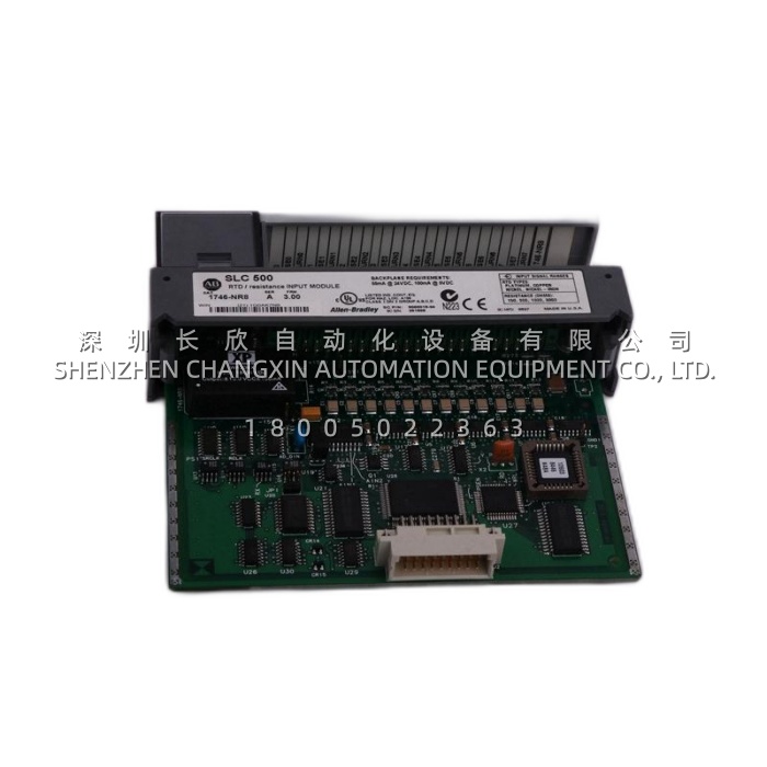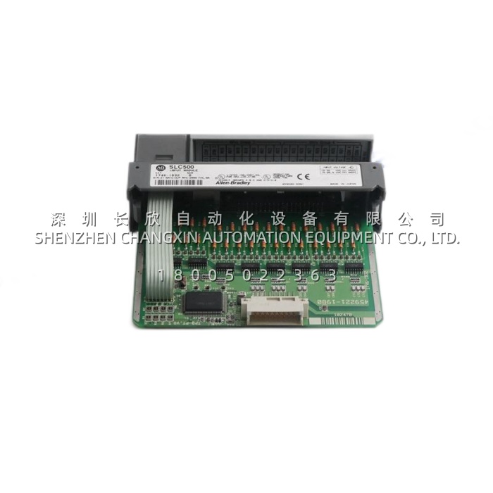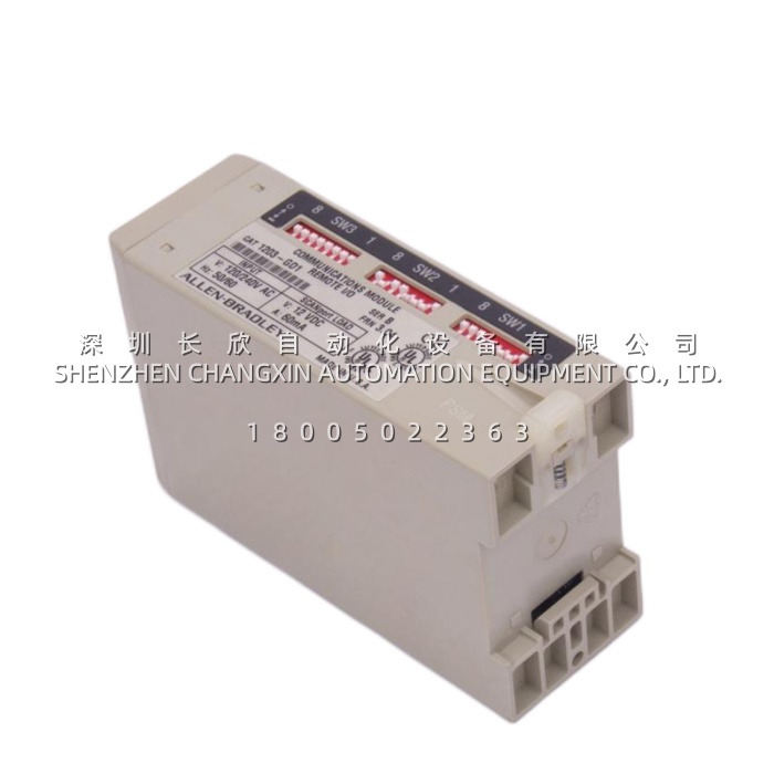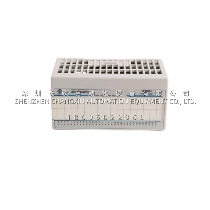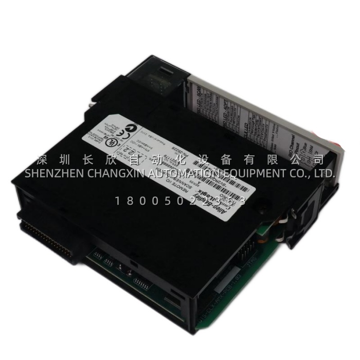
Allen-Bradley 845H-SJDZ24FWY2C Optical Incremental Encoder缩略图

Allen-Bradley 845H-SJDZ24FWY2C Optical Incremental Encoder

Allen-Bradley 845H-SJDZ24FWY2C Optical Incremental Encoder插图


Application Scenarios

On a high-speed packaging line, a 845H-SJDZ24FWY2C was mounted directly to the main drive motor of a film-feed axis controlled by a PowerFlex 755 drive. The encoder‘s HTL differential outputs (A, /A, B, /B, Z, /Z) transmitted 1024 pulses per revolution over a 12-meter cable run through an electrically noisy cabinet, maintaining signal integrity where a previous single-ended encoder had produced position drift and intermittent drive faults. The 845H-SJDZ24FWY2C’s square flange and 3/8-inch keyed stainless steel shaft matched the motor‘s existing mounting interface, allowing direct replacement without adapter hardware. After commissioning, the drive’s position loop achieved stable operation at line speeds up to 1,500 RPM, and the IP66-rated shaft seal eliminated the moisture ingress failures that had plagued the previous encoder in the washdown-adjacent environment.


Parameter

Parameter Value / Description
Product Model 845H-SJDZ24FWY2C
Manufacturer Allen-Bradley / Rockwell Automation
Product Category Optical Incremental Encoder (Bulletin 845H, Size 25)
Resolution 1024 Pulses Per Revolution (PPR)
Output Configuration Differential Line Driver, 5 VDC RS-422 compatible
Output Signals A, /A, B, /B, Z, /Z (quadrature + complementary + gated zero index)
Quadrature Phase 90° ±22°; Channel A leads B in CCW rotation
Power Supply 8–24 VDC unregulated
Frequency Response 210 kHz (data and zero index)
Operating Speed 6000 RPM maximum
Shaft Configuration 3/8 in. (9.517 mm) diameter, stainless steel
Shaft Loading Axial: 89 N (20 lb); Radial: 178 N (40 lb)
Mounting Square Flange (Size 25)
Connection Type Radial (side) M12 connector, 8-pin A-coded, with mating connector
Housing Rating NEMA Type 4, 13; IP66 (IEC 529)
Operating Temperature 0°C to +60°C
Shock / Vibration 50 g (11 ms) / 20 g (4–2000 Hz)
Weight Approx. 0.48 kg
Lam Research 839-800327-315 Electrostatic Chuck – 300mm Bipolar ESC for 2300 Metal Etch Systems缩略图

Lam Research 839-800327-315 Electrostatic Chuck – 300mm Bipolar ESC for 2300 Metal Etch Systems

Lam Research 839-800327-315 Electrostatic Chuck – 300mm Bipolar ESC for 2300 Metal Etch Systems插图


Application Scenarios

A wafer fab operating a fleet of Lam 2300 Exelan dielectric etch chambers for oxide and low-k interconnect processes began noticing a familiar pattern of drift after thousands of wafers. The maintenance team saw the helium backside leak rate climbing slowly, dechuck time stretching from under a second to several seconds, and edge critical-dimension (CD) uniformity widening by a nanometre or two per quarter. The difficulty was that none of these signatures pointed clearly to the ESC: a rising helium leak resembled a gas box or MFC issue, longer dechuck time suggested an ESC power supply fault, and higher particle counts looked like a chamber-clean problem. By identifying and replacing the worn 839-800327-315, the team addressed the root cause directly—restoring wafer flatness, helium sealing, clamping force, and particle performance in one intervention. This case illustrates why the 839-800327-315​ is so valuable in a legacy 2300 fleet: it resolves ambiguous chamber drift at the component level and avoids months of lost availability while chasing the wrong subsystem.


Parameter

Main Parameters Value / Description
Product Model 839-800327-315
Manufacturer Lam Research Corporation (USA)
Product Category Electrostatic chuck (ESC) assembly – wafer clamping and lower electrode
Platform Lam 2300 series etch systems; confirmed on 2300 Exelan / Versys Metal
Wafer Size 300mm (12-inch)
ESC Type Bipolar, ceramic, embedded big pin
Dielectric Material Sintered ceramic (alumina or aluminium nitride by configuration; verify by revision)
Clamping Principle Electrostatic attraction across a ceramic dielectric (Coulomb / Johnsen-Rahbek; confirm revision)
Process Application Dry plasma etch: dielectric, oxide, low-k, metal films
Backside Thermal Control Helium backside cooling through grooves and sealing lands
Approximate Weight 7.25 kg
Cross-Reference 715-800327-315​ (same chuck traded under alternate number)
Service Status Out of OEM production; supplied as new surplus, tested used, or professionally reworked


Technical Principles and Innovative Values

  • Innovation Point 1: Uniform Clamping Without Mechanical Contact​ – A mechanical edge clamp grips only the wafer perimeter, creates local stress, shadows the touched region, and leaves the wafer centre poorly contacted. The 839-800327-315​ distributes holding force across the full 300mm backside, so the wafer sits flat against the temperature-controlled face. In plasma etch, where ion trajectory and local temperature vary by position, this uniform contact is a prerequisite for uniform etching.
  • Innovation Point 2: The Chuck Is the Lower Electrode​ – In the etch chamber, the 839-800327-315​ carries the RF bias that drives ions into the wafer surface. Its dielectric thickness, ceramic integrity, and RF return path all shape the plasma sheath directly. This makes the ESC a process component rather than a simple handling part.
  • Innovation Point 3: Integrated Thermal Management via Helium Backside Cooling​ – The chuck face incorporates cooling grooves and sealing lands, allowing helium to transport heat from the wafer backside. Stable wafer temperature during exothermic plasma reactions protects critical dimension control and repeatability.
  • Innovation Point 4: Big-Pin Embedded Interface for Repeatable RF and He Delivery​ – The embedded big pin design provides a robust, precision-aligned connection for RF, heater, and helium paths. This simplifies re-installation and preserves consistent electrical and thermal performance across maintenance cycles.
ARCA 812.201-M DN50 Pneumatic Control Valve for Chemical, Power and District Heating Applications缩略图

ARCA 812.201-M DN50 Pneumatic Control Valve for Chemical, Power and District Heating Applications

ARCA 812.201-M DN50 Pneumatic Control Valve for Chemical, Power and District Heating Applications插图


Application Scenarios:

A district heating operator was fighting a chronic problem on a secondary-network heat exchanger: the existing DN50 control valve could not hold return temperature within specification at low night-time load, and it wept continuously through the stuffing box. Every re-pack meant a shutdown window, every seat repair meant pulling the body out of the line, and each plant visit required a technician to bend new tubing between the positioner and the actuator because the old design had no integrated air path.The retrofit installed the 812.201-M​ with an equal-percentage plug and a metal-seated clamping seat. The 812.201-M​ delivered fine resolution at small openings where the loop actually operates, and its PTFE V-ring packing with corrosion-resistant pre-load spring removed the emission problem that had driven the maintenance schedule. Commissioning was shortened dramatically because the positioner mounts to the actuator through the integrated air duct — no external tubing, no leak paths, no re-bending.The same value proposition appears across reactor jacket temperature control in fine chemicals, boiler feedwater and steam pressure reduction in power generation, thermal-oil circuits in food processing, and gas pressure let-down stations. In every case the pain point is identical: a valve that cannot hold setpoint across a wide turndown, leaks at the stem, and costs too many hours to service. The 812.201-M​ is engineered specifically to remove those three costs.


Parameter:

Main Parameters Value / Description
Product Model 812.201-M DN50
Manufacturer ARCA Regler GmbH (ARCA Flow Group)
Product Category Pneumatic straight-way globe control valve (sliding stem, spring-return)
Nominal Size DN 50 / NPS 2″ — the workhorse size for heat exchanger, steam and process liquid loops
Pressure Rating PN 16 / PN 25 / PN 40 (per body version); ANSI Class 150 / 300 available
Body Material Cast steel 1.0619 (A216 WCB) or stainless 1.4408 (A351 CF8M); further alloys on request
Trim / Plug Parabolic contoured plug P1 in 1.4571 (316Ti); hardened 1.4112 or nitrided versions for erosive duty
Flow Characteristic Equal percentage or linear — chosen to match installed process gain
Rangeability 50:1 — controllable flow from full load down to roughly 2 % without loss of stability
Seat Leakage IEC 60534-4 Class IV (≤ 0.01 % of Kvs) metal seated; Class V or Class VI soft seated optional
Flow Coefficient Kvs Typically 25–40 m³/h at DN50 depending on selected seat diameter and trim
Actuator Type ARCAPAQ 812 multi-spring diaphragm actuator, spring return fail-safe
Diaphragm Effective Area MF I: 320 cm² / MF III: 720 cm² — selectable thrust class for the same footprint
Control Force Air-to-close up to 14.4 kN (MF I) and up to 32.4–35.2 kN (MF III); spring force 4.8–22 kN
Control Signal / Air Supply 0.2–1.0 bar standard (other ranges available); max. signal pressure 6 bar; supply typically 1.4–7 bar
Rated Stroke 20 mm standard (30 / 60 mm available in the 812 series)
Operating Temperature -10 °C to +400 °C (1.0619 body); -29 °C to +400 °C (1.4408 body, down to -196 °C in low-temp design)
Ambient Temperature (actuator) -20 °C to +80 °C, optionally -40 °C to +80 °C
Stem Seal Low-maintenance PTFE V-ring packing with fine sealing element, TA-Luft / ISO 15848 qualified, or bellows seal option
End Connection Flanged to EN 1092-1 or ASME B16.5; face-to-face EN 558 Series 1 (PN 16/40)
Positioner Interface VDI/VDE 3847 integrated air duct mounting — no external piping, no linkages


Technical Principles and Innovative Values:

Innovation Point 1: Patented Clamping Seat with Quick-Exchange SystemThe seat ring of the 812.201-M​ is clamped, not threaded. It is held in the force bypass of the body and can be lifted out and replaced without special tools, and the symmetrical ring can be turned over and reused — ARCA’s double-life principle. In practice this halves seat-ring consumption and turns a job that once needed a machine shop into one that needs a torque wrench and twenty minutes.Innovation Point 2: PTFE Soft Seal with Metal Secondary SealUnlike conventional designs where the soft element sits on the plug, the 812.201-M​ seats a PTFE ring flexibly supported by an elastomer O-ring in the seat, backed by a metal-to-metal secondary seal between plug and seat ring. The metal stop prevents the PTFE from being plastically deformed by excessive closing force, which is what normally kills soft-seated valves early. The outcome is Class VI tightness with a service life normally associated with metal seats.Innovation Point 3: Self-Adjusting Stem PackingThe standard packing set combines graphite-PTFE and pure PTFE V-rings with a corrosion-resistant pre-load spring beneath the packing. As the packing settles, the spring maintains sealing force instead of relying on a technician to re-tighten the gland. Certified to TA-Luft and ISO 15848 over -46 °C to +200 °C with a special PTFE compound, the 812.201-M​ addresses fugitive emissions at the design stage rather than through an operating procedure.Innovation Point 4: Integrated Air Duct and Linkage-Free FeedbackSignal air travels to the diaphragm chamber through internal channels in the yoke, and the positioner couples to the actuator stem without external tubing or feedback linkages. Fewer parts means fewer leak paths, no tube vibration cracking, and no lost motion in the feedback path. The 812.201-M​ can have its positioner mounted and calibrated in three to four minutes in-line, using only the local keys on the positioner — no handheld communicator, no removal from the pipe.

ABB PPC907BE Control Board – The Computational Core of ACS2000 Medium Voltage Drives缩略图

ABB PPC907BE Control Board – The Computational Core of ACS2000 Medium Voltage Drives

ABB PPC907BE Control Board – The Computational Core of ACS2000 Medium Voltage Drives插图


Application Scenarios

Consider a 2 MW induced draft fan at a thermal power plant, running continuously to maintain furnace pressure. When the medium voltage drive loses synchronization with its power stage due to a control board communication fault, the motor can trip offline instantly, forcing an unplanned outage. The ABB PPC907BE addresses this exact vulnerability by maintaining deterministic timing across the CAN bus and fiber optic links that govern IGBT gate pulses. In cement plants, where high-voltage motors drive kiln and mill equipment through dusty, high-temperature environments, this board’s conformal-coated PCB and IP20-rated protection ensure the control logic remains stable despite airborne contaminants and thermal stress . The board doesn’t merely control a motor—it protects the entire production chain from the cascade effects of drive failure.


Parameter

Parameter Value / Description
Product Model ABB PPC907BE
Manufacturer ABB (Switzerland)
Product Category Drive Control Board / Main Controller
System Compatibility ACS2000 Frames 1, 2, and 3
Working Voltage 24 V DC (19.2–28.8 V DC range)
Power Consumption ≤ 4.5 W (typical operation)
Processor Industrial-grade PowerPC e750, 800 MHz
Memory 512 MB RAM, 2 MB flash program storage
Communication Interfaces Ethernet, CAN Bus, RS-232/RS-485, Profibus DP
Operating Temperature -20°C to +60°C (cabinet interior conditions)
Storage Temperature -40°C to +85°C
Protection Class IP20 (cabinet-mounted only)
Weight Approximately 0.87 kg
Installation Rack-mounted plug-in, frame-positioned


Technical Principles and Innovative Values

Innovation Point 1 – Deterministic Motor Control Architecture: The ABB PPC907BE executes direct torque control (DTC) algorithms on a dedicated 800 MHz PowerPC processor, computing stator flux and torque states every 25 microseconds. This real-time computational capacity enables torque response times below 5 milliseconds without encoder feedback—a differentiator against drives requiring external position sensors and additional wiring.

Innovation Point 2 – Integrated Fault Capture and Waveform Storage: Unlike control boards that merely report fault codes, the ABB PPC907BE stores multiple pre-fault and post-fault waveform datasets locally. Engineers can retrieve complete current, voltage, and switching state profiles through the Ethernet diagnostic port, reducing mean-time-to-diagnosis from hours to minutes in medium voltage drive service.

Innovation Point 3 – Optical Isolation Boundary Management: The board maintains galvanic separation between its 24 V control electronics and the 4 kV medium voltage power stage through optical isolation interfaces. This design eliminates ground loop pathways that could inject destructive transients into the control logic during switching events .

Innovation Point 4 – Firmware-Configurable Protocol Selection: Ethernet, CANopen, and Profibus protocols are all supported through firmware configuration blocks rather than hardware jumper changes. A single ABB PPC907BE board can serve different system integration requirements across project sites without physical modification .

Honeywell 800XP-SM32 Standard Orientation I/O Subsystem Mounting Kit for Experion PKS HPM缩略图

Honeywell 800XP-SM32 Standard Orientation I/O Subsystem Mounting Kit for Experion PKS HPM

Honeywell 800XP-SM32 Standard Orientation I/O Subsystem Mounting Kit for Experion PKS HPM插图


Product Overview

The Honeywell 800XP-SM32​ is a single-width I/O subsystem mounting kit that forms the mechanical and electrical backbone of a High-Performance Process Manager (HPM) I/O station within the Experion PKS architecture. Rather than processing signals itself, the Honeywell 800XP-SM32​ provides the card cage, the backplane bus and the power distribution network that allow a set of individual 800XP I/O modules to operate as one coherent, addressable node. Every analog input, analog output, digital input and digital output card in the station plugs into this backplane, draws its supply from it, and exchanges data with the HPM controller through it.The “Standard Orientation” designation matters more than it first appears: it defines the direction in which the module connectors face when the rack is installed in a cabinet, and therefore dictates cable routing, field wiring access and cooling airflow. Choosing the Honeywell 800XP-SM32​ in standard orientation keeps the cabinet layout consistent with the majority of existing HPM installations, which is exactly why maintenance teams standardise on it for expansions and like-for-like replacements.In a distributed control system, the rack is the least glamorous but most critical hardware element: if the backplane is unstable, no amount of intelligence in the modules above it can compensate. The Honeywell 800XP-SM32​ is engineered for continuous duty in control-room and field-shelter environments, supports connection of redundant power modules so that a single supply failure does not drop the node, and reserves positions for system status indication so operators can see node health at a glance. For plants extending an Experion PKS system, it is the foundation on which additional measurement and control capacity is built.


Technical Specifications

Parameter Name Parameter Value
Product Model 800XP-SM32​ (Standard Orientation)
Manufacturer Honeywell
Product Type I/O Subsystem Mounting Kit / Backplane Chassis
Platform Experion PKS, High-Performance Process Manager (HPM)
Mounting Orientation Standard orientation (module connectors face left as installed; reverse variant available separately)
Supported I/O Modules 800XP series I/O modules – analog input, analog output, digital input, digital output and specialty cards
Module Capacity Limited by backplane bus loading and installed power budget (confirm slot count in the system design)
Backplane Function Distributes power to all slots and carries high-speed data between I/O modules and the HPM controller
Power Supply Connection Accepts redundant 24 V DC power modules (for example the 800XP-PS class supply)
Controller Interface Dedicated cable link to the HPM controller or to an I/O link interface module
Status Indication Provision for system status LED indication on the rack assembly
Mounting Method Standard 19-inch control cabinet / cabinet rail mounting
Operating Environment 0 °C to +60 °C cabinet ambient, 5 % to 95 % relative humidity non-condensing


Main Features and Advantages

Standardised mechanical platform: The 800XP-SM32​ gives every 800XP I/O module a defined, repeatable home. Guide rails, keyed slot mechanics and a rigid backplane keep cards seated correctly even where cabinets are subject to vibration from nearby plant equipment, and the standard orientation means that a technician who has worked on one HPM node can work on any other without re-learning the wiring geometry. Standardisation shortens both commissioning and fault-finding, because module position, addressing and cable entry follow the same pattern across the whole plant.Clean power distribution: The backplane of the 800XP-SM32​ is designed as a low-impedance power distribution path, not simply a connector strip. Supply and return are routed to every slot with filtering that keeps noise from digital switching and field-side transients away from sensitive analog channels — a practical requirement when a single rack may carry thermocouple inputs alongside solenoid outputs. Support for redundant power modules means the node can survive the loss of one supply without dropping the I/O, which is what makes the station suitable for continuous process service.Service-friendly layout: Because the 800XP-SM32​ separates power, data and field wiring physically, modules can be replaced with the node energised in appropriately configured redundant systems, and field terminations stay untouched while a card is swapped. Reserved status LED positions give immediate local indication of rack and module health, so a fault can be localised before a laptop is even opened.Investment protection: The 800XP-SM32​ allows a plant to expand I/O point by point. Adding a temperature loop or a new valve command does not require a new controller, a new network drop or a new cabinet — only a spare slot in an existing rack and the corresponding module, which keeps expansion costs predictable over the life of the DCS.

800x-alp_800f_pb_22_mm_accessory缩略图

800x-alp_800f_pb_22_mm_accessory

800x-alp_800f_pb_22_mm_accessory插图


Application Scenarios

Consider a packaging machine manufacturer that produces custom control panels for food processing lines. Each panel requires dozens of illuminated push buttons with varying functions—start, stop, reset, and mode selection—distributed across multiple machine sections. When a customer requests a change from momentary start buttons to maintained mode-select buttons two weeks before delivery, the production team faces a costly rework of pre-wired panels. With the 800X-ALP-800F-PB-22MM actuator head paired to the appropriate 800F contact block, the modification becomes a simple component swap: the actuator head disconnects from the front without disturbing panel wiring, and a different contact block is clicked into place from behind. What would have required three days of panel rewiring is completed in under an hour. This modularity directly addresses the pain point of late-stage design changes and field upgrades, where the cost of rework often exceeds the value of the switches themselves.


Parameter

Parameter Value/Description
Product Model 800X-ALP-800F-PB-22MM
Manufacturer Eaton (Cutler-Hammer)
Product Category Illuminated Push Button Actuator Head
Compatibility Eaton 800F series switch bodies only
Actuator Type Flat push button (PB)
Mounting Diameter 22 mm standard panel cutout
Illumination Green LED integrated into actuator
LED Power Source Supplied by 800F switch body via multi-pin connection
Lens Material Translucent plastic with permanent legend capability
Protection Rating IP65 or higher when properly installed
Mechanical Life ≥ 1,000,000 operations
Operating Temperature -25°C to +70°C
Certifications cULus, CE


Technical Principles and Innovative Values

Innovation Point 1: Tool-Free Actuator Replacement. The 800X-ALP-800F-PB-22MM uses a plug-in connection to the 800F switch body, allowing the actuator head to be removed from the panel front by hand after the locking ring is released. This design eliminates the need to access the rear of the panel for routine actuator replacement, reducing maintenance time from 15 minutes to under 2 minutes per switch in densely packed enclosures.

Innovation Point 2: Integrated LED with Body-Sourced Power. The green LED within the 800X-ALP-800F-PB-22MM derives its power from the 800F switch body through a dedicated pin connection, rather than requiring separate external wiring to the actuator head. This architecture simplifies panel wiring and ensures that LED status accurately reflects the contact state or control circuit condition as configured at the body level.

Innovation Point 3: Modular Separation of Function and Interface. The 800X-ALP-800F-PB-22MM embodies the 800F system’s core philosophy: the contact block handles electrical switching, while the actuator head handles human interaction. This separation allows a single actuator design to work with momentary, maintained, or multi-circuit contact blocks, and it enables field replacement of worn lenses or failed LEDs without touching the electrical connections.

Innovation Point 4: Permanent Legend Capability. The translucent button cap of the 800X-ALP-800F-PB-22MM accepts permanent marking through laser etching or molded legends, ensuring that labels remain legible after years of operation. This contrasts with adhesive labels that peel or fade in industrial environments, reducing the risk of operator error caused by ambiguous button identification.

800x-alp_800f_pb_22_mm_accessory插图1

Fluke 773 Loop Clamp Meter with Scaled mA Output for Datalogging DMMs缩略图

Fluke 773 Loop Clamp Meter with Scaled mA Output for Datalogging DMMs

Fluke 773 Loop Clamp Meter with Scaled mA Output for Datalogging DMMs插图


Product Overview

The Fluke 773​ is the flagship of Fluke’s milliamp process clamp meter family, a handheld, battery-powered instrument built specifically for technicians and instrumentation engineers who work on 4-20 mA process control loops. Unlike a conventional multimeter, which forces you to open the circuit and insert the meter in series, the Fluke 773​ measures loop current non-invasively: you simply clamp the jaw around a single signal wire and read the current, so the process keeps running and the controller never loses its input. This single capability is why the Fluke 773​ has become the default troubleshooting tool in process plants, water and wastewater facilities, HVAC and building automation systems, and anywhere analog instrumentation is dense.What elevates the Fluke 773​ above the 771 and 772 in the same family is its full signal-chain capability. In addition to clamp-based and in-circuit mA measurement, it sources 4-20 mA for driving control system inputs, I/P converters and valve positioners; it simulates 4-20 mA while accepting an external loop supply of up to 50 V DC; it provides 24 V loop power so a transmitter can be energized and tested on the bench; and it both measures and sources DC voltage, verifying 24 V supplies and testing 1-5 V or 0-10 V input devices. Accuracy is best-in-class at 0.2% with 0.01 mA resolution and sensitivity, and the dual backlit display shows both the absolute mA value and the percentage of 4-20 mA span simultaneously.Designed for real panel work, the Fluke 773​ features a detachable clamp on an extension cable that reaches wires buried in crowded terminal cabinets, a measurement spotlight that illuminates dark enclosures, a Hold function for capturing drifting readings, and automatic 25% step or linear ramp output for remote testing and stroke checks. Powered by four AA batteries and rated IP40, it is a genuinely portable one-tool replacement for a loop calibrator, a DMM and a current source on routine service calls.


Technical Specifications

Parameter Name Parameter Value
Product Model Fluke 773​ (FLUKE-773)
Manufacturer Fluke Corporation
Product Type Milliamp Process Clamp Meter / Loop Calibrator
Series / Platform Fluke 77x mA Process Clamp Meter family (771 / 772 / 773)
mA Measurement (clamp) 0 to 20.99 mA, accuracy 0.2% + 5 counts, resolution 0.01 mA
mA Measurement (clamp, extended) 21.0 to 100.0 mA, accuracy 1% + 5 counts
mA Measurement (in series, test jacks) 0 to 24.00 mA, accuracy 0.2% + 2 counts
mA Source 0 to 24.00 mA, accuracy 0.2% + 2 counts; max drive 24 mA into 1,000 Ω
mA Simulate 0 to 24.00 mA, accuracy 0.2% + 2 counts; max external voltage 50 V DC
DC Voltage Source 0 to 10.00 V DC, accuracy 0.2% + 2 counts; 2 mA max drive current
DC Voltage Measure 0 to 30.00 V DC, accuracy 0.2% + 2 counts
Loop Power 24 V DC loop supply for powering and testing transmitters
Output Modes Linear ramp or automatic 25% step; scaled mA output proportional to measured clamp current
HART Compatibility Built-in 250 Ω resistor selectable in source/simulate mode for HART communication
Display Dual backlit LCD showing mA reading and percentage of 4-20 mA span
Measurable Conductor Diameter 4.5 mm (0.177 in) maximum
Power / Battery Life 4 × AA 1.5 V alkaline (IEC LR6); approx. 12 hours in mA source into 500 Ω
Operating Temperature −10 °C to +50 °C (storage −25 °C to +60 °C)
Operating Humidity <90% at <30 °C; <75% at 30 to 55 °C
Operating Altitude 0 to 2,000 m
Dimensions / Weight 44 × 70 × 246 mm; 410 g
Ingress Protection IP40; 1 m drop tested (excluding clamp)
Safety & EMC EN/IEC 61010-1, EN/IEC 61010-2-032, CE marked; EN 61326-1 EMC
Warranty 3 years on electronics, 1 year on cable and clamp assembly


Main Features and Advantages

Non-invasive loop measurement: The defining advantage of the Fluke 773​ is that it reads 4-20 mA signals without breaking the loop, which Fluke rates as roughly five times faster than the traditional DMM method of opening the circuit and inserting test leads. Because the process never stops, intermittent faults that only appear under live conditions stay visible, and there is no risk of leaving a loop open after the test. The Fluke 773​ resolves down to 0.01 mA with 0.2% accuracy, sensitive enough to detect the small drift that indicates a failing transmitter or a wetted terminal.Measure, source, simulate and power in one tool: Where a basic clamp meter only reads, the Fluke 773​ closes the whole diagnostic circle. It sources 0-24 mA into loads up to 1,000 Ω to drive and stroke a valve or test a PLC analog input. In simulate mode it behaves as a two-wire transmitter, sinking current from an external supply of up to 50 V DC so a control card can be verified without a real field device. The 24 V loop power supply lets you energize a transmitter on the bench and simultaneously read its output in-circuit, which turns a two-person, two-instrument job into a one-person task.Voltage capability for mixed-signal panels: The Fluke 773​ also measures 0-30 V DC and sources 0-10 V DC, so the same instrument checks 24 V power supplies and validates the 1-5 V and 0-10 V inputs still common in building automation, drives and older DCS cards. Automatic linear ramp and 25% step output make stroke testing and remote calibration straightforward, and the Hold button freezes a fluctuating reading so you can write it down.Built for the cabinet, not the bench: A detachable clamp jaw on an extension cable lets the Fluke 773​ reach a single wire in a dense terminal block, while the measurement spotlight lights up the wire you are trying to see. The dual backlit display, auto-off and backlight timeout extend practical battery life, and the scaled mA output mirrors the clamped signal so a logging DMM such as the Fluke 289 can record a loop trend for hours without interrupting it.

750-p5-g5-s5-hi-a20-r-e_ge_relay_module缩略图

750-p5-g5-s5-hi-a20-r-e_ge_relay_module

750-p5-g5-s5-hi-a20-r-e_ge_relay_module插图


Technical Specifications

Parameter Name Parameter Value
Product Model 750-P5-G5-S5-HI-A20-R-E
Manufacturer GE Multilin (GE Vernova / GE Grid Solutions)
Product Type Feeder Management Relay / Digital Protection IED
Series GE Multilin 750/760 Feeder Management Relays
Phase CT Rating 5 A (P5)
Zero-Sequence CT Rating 5 A (G5)
Sensitive Ground CT Rating 5 A (S5)
Control Power 88–300 VDC / 70–265 VAC, 48–62 Hz (HI)
Analog Outputs 8 × 4–20 mA (A20)
Breaker Closed Indicator Red LED (R)
Display Enhanced LCD with expanded keypad (E)
Communication Protocols Modbus RTU, DNP 3.0, IEC 60870-5-103
Serial Ports RS232 (front), RS485/RS422 (rear)
Operating Temperature -40°C to +70°C
Mounting Draw-out relay, panel or rack mount
Weight Approximately 3.86 kg


Main Features and Advantages

Comprehensive feeder protection in a single platform: The 750-P5-G5-S5-HI-A20-R-E integrates time-overcurrent (TOC) and instantaneous overcurrent (IOC) protection with 15 selectable curve shapes including FlexCurves, directional overcurrent elements, negative-sequence overcurrent, undervoltage, overvoltage, and frequency protection . This consolidation reduces panel space, wiring complexity, and the coordination burden associated with multiple discrete relays, while the draw-out construction allows rapid replacement without disturbing rear field wiring.

Sensitive ground fault detection for high-impedance systems: The “S5” sensitive ground input on the 750-P5-G5-S5-HI-A20-R-E enables detection of low-level leakage currents that conventional ground CTs cannot reliably capture. This is particularly valuable for feeders on high-impedance grounded or resonant-grounded systems, where fault currents may be limited to a few amperes and conventional protection would remain blind to developing insulation degradation .

Analog output flexibility: The 750-P5-G5-S5-HI-A20-R-E provides eight isolated 4–20 mA analog outputs, enabling direct interfacing with SCADA, DCS, or plant monitoring systems without additional transducers. Measured or calculated parameters—including phase currents, power, frequency, and thermal loading—can be mapped to these outputs for real-time remote indication .

Enhanced local interface: The “E” suffix denotes the enhanced display configuration, featuring a larger LCD and expanded keypad for on-site navigation of metering, status, maintenance, trip counter, and arcing current data. The 750-P5-G5-S5-HI-A20-R-E supports both hardware and passcode security to prevent unauthorized setpoint changes .


Application Field

The 750-P5-G5-S5-HI-A20-R-E is deployed primarily in distribution substations and industrial facilities where reliable feeder protection is critical to operational continuity. In utility networks, it serves as the primary protection relay for medium-voltage feeders originating from substation busbars, providing overcurrent and directional protection that can discriminate between forward and reverse faults—essential in ring-bus or distributed generation configurations where fault current may flow in either direction .

Industrial plants—including petrochemical complexes, steel mills, and manufacturing facilities—use the 750-P5-G5-S5-HI-A20-R-E to protect incoming feeders, bus ties, and transformer bays. The sensitive ground input is particularly relevant in facilities with resistance-grounded or ungrounded distribution systems, where early detection of insulation faults prevents escalation to phase-to-phase faults and unplanned outages.

Renewable energy installations, including wind and solar farms, employ the 750-P5-G5-S5-HI-A20-R-E for collector feeder protection. Its directional overcurrent capability supports coordination in systems with multiple generation sources, while the 4–20 mA outputs provide analog telemetry to plant control systems without requiring protocol gateways. The relay’s wide temperature range and optional conformal coating make it suitable for outdoor enclosures and remote substations.

GE Multilin 750-P5-G5-S5-HI-A1-R-E-H​ Feeder Management Relay — 5 A Phase, Ground and Sensitive Ground CT Inputs缩略图

GE Multilin 750-P5-G5-S5-HI-A1-R-E-H​ Feeder Management Relay — 5 A Phase, Ground and Sensitive Ground CT Inputs

GE Multilin 750-P5-G5-S5-HI-A1-R-E-H​ Feeder Management Relay — 5 A Phase, Ground and Sensitive Ground CT Inputs插图


Product Overview

The GE Multilin 750-P5-G5-S5-HI-A1-R-E-H​ is a microprocessor-based feeder management relay from the well-known 750/760 Feeder Management Relay​ platform (also referenced as the SR750 series), designed to deliver complete protection, control, metering and monitoring for medium-voltage utility and industrial distribution feeders. In a single drawout case, the 750-P5-G5-S5-HI-A1-R-E-H​ combines phase, ground and sensitive ground overcurrent elements with voltage, frequency, directional, breaker-failure and synchronism-check functions, so a single device replaces what used to require a panel full of discrete electromechanical relays. By continuously sampling the current and voltage waveforms and executing high-speed trip logic, it isolates faulted cable sections and transformers before thermal damage accumulates, and it records what happened so engineers can prove it afterwards.The order code of the 750-P5-G5-S5-HI-A1-R-E-H​ defines its exact factory build, and reading that code is the fastest way to understand the device. P5 specifies 5 A phase current inputs, G5 specifies 5 A zero-sequence (ground) current inputs, and S5 specifies a 5 A sensitive ground input — the third channel being the one that makes low-magnitude, high-impedance earth faults on cable feeders detectable at all. HI defines the wide-range control power supply (88 to 300 V DC, 70 to 265 V AC at 48 to 62 Hz), which lets the same unit run from a 125 V or 250 V station battery or from an AC auxiliary supply without a variant change. A1 provides the analog output channel set (0–1 mA class), R gives a red breaker-closed LED for unambiguous local status, E denotes the enhanced display — the larger backlit LCD and improved keypad introduced with the V6.00 generation — and H is the harsh-environment option, meaning the internal boards carry a factory-applied conformal coating.In system terms, the 750-P5-G5-S5-HI-A1-R-E-H​ sits at the primary protection layer of a feeder bay and doubles as an intelligent electronic device (IED) for SCADA. It presents measured values, breaker status, trip counters, sequence-of-events records and oscillography over RS232, RS485 and Ethernet using Modbus RTU/TCP and DNP 3.0, and it is configured and commissioned through GE’s EnerVista 750/760 Setup software. Because it communicates as comfortably as it protects, it is equally at home in a utility substation, an industrial switchgear lineup, or a brownfield panel where an ageing electromechanical scheme is being upgraded one bay at a time.


Technical Specifications

Parameter Name Parameter Value
Product Model 750-P5-G5-S5-HI-A1-R-E-H
Manufacturer GE Multilin (General Electric / GE Vernova Grid Solutions)
Product Type Digital Feeder Management and Protection Relay (SR750 platform)
Series / Platform 750 / 760 Feeder Management Relay (drawout case)
Phase Current Inputs (P5) 5 A nominal CT secondary (Ia, Ib, Ic); 1–50000 A primary range
Zero-Sequence Ground Input (G5) 5 A nominal CT secondary
Sensitive Ground Input (S5) 5 A nominal, high-sensitivity earth fault channel
Control Power (HI) 88 – 300 V DC / 70 – 265 V AC, 48 – 62 Hz; 25 VA nominal, 35 VA max
Voltage Inputs Up to 273 V phase-to-neutral full scale; ±0.25 % accuracy (11–130 V)
Analog Outputs (A1) Eight 0–1 mA analog output channels (programmable measured value)
Logic Inputs / Outputs 14 logic inputs (contact or virtual, plus 6 virtual-only); 8 output relays
Communication Ports RS232 (front), RS485 / RS422 (rear), optional 10Base-T Ethernet
Protocols Supported Modbus RTU, Modbus TCP/IP, DNP 3.0
Protection Functions 50P/51P, 50G/51G, 50SG/51SG, 67P/67N/67G/67SG, 46, 27/59, 59N, 81U/O, 32, 25, 50BF, thermal overload
Display / Indication (E / R) Enhanced backlit LCD, 40-character, improved keypad; red breaker-closed LED
Oscillography / Records Up to 64 cycles waveform capture, sequence-of-events (SOE) log, demand and load history
Operating Temperature −40 °C to +60 °C
Dimensions / Weight Approx. 20.8 × 22 × 24.6 cm / approx. 7.6 kg (shipping weight varies by case)
Certifications CE, UL, CSA; IEC 255 and applicable ANSI/IEEE relay standards


Main Features and Advantages

Three independent current channels, including a genuinely sensitive ground path: The P5, G5 and S5 options on the 750-P5-G5-S5-HI-A1-R-E-H​ are not redundant copies of the same input. Phase currents feed overcurrent, negative-sequence and directional elements; the standard ground input handles solid and low-impedance earth faults; and the sensitive ground channel is what detects the low-level, often intermittent earth faults typical of high-impedance grounded and cable-heavy networks. In practice, this is the difference between a relay that trips on a fault and a relay that sees the fault developing — arcing insulation, moisture ingress, a deteriorating cable joint — before it escalates into a feeder outage.One relay, an entire protection panel: The 750-P5-G5-S5-HI-A1-R-E-H​ carries an unusually broad ANSI function set — 50/51 phase, ground and sensitive ground, 67 directional variants, 46 negative sequence, 27/59 voltage, 81 frequency, 32 reverse power, 25 synchronism check and 50 breaker failure — plus metering, demand logging, breaker wear monitoring and programmable logic. Consolidating these functions into one IED reduces panel wiring, removes inter-relay coordination wiring errors, and gives protection engineers a single settings file to manage, version and audit instead of a dozen dial-setting sheets.Engineering and commissioning features that save real hours: With the E option, the 750-P5-G5-S5-HI-A1-R-E-H​ presents a 40-character backlit display and a logically grouped keypad, so a technician can read measured values, actual setpoints and fault messages without a laptop. Through EnerVista 750/760 Setup, the same engineer gets dual-cursor oscillography with delta measurement, zoom and playback for precise post-fault analysis, quick-connect serial setup, and the ability to configure multiple relays from one workspace. Four independent setting groups allow the same hardware to cover normal, emergency, seasonal and maintenance operating modes without re-downloading settings.Built for the environment it actually lives in: The H suffix on the 750-P5-G5-S5-HI-A1-R-E-H​ means the internal assemblies are conformal coated at the factory. That transparent polymer barrier protects against conductive dust, humidity, salt spray and the mildly corrosive atmospheres found in chemical plants, pulp and paper mills, wastewater facilities, mines and offshore platforms — environments where an unprotected relay board slowly loses reliability long before it visibly fails. Combined with the wide-range HI control supply, which tolerates the full span of a station battery from equalise charge down to end-of-discharge, and a −40 °C to +60 °C operating range, the unit is specified for the real conditions of outdoor switchgear and industrial substations rather than for a laboratory bench.

GE Multilin 750-P5-G5-S5-HI-A1-R-E-H​ Feeder Management Relay — 5 A Phase, Ground and Sensitive Ground CT Inputs插图1

750-p5-g5-d5-hi-a20-r-e-h_ge_feeder_management_relay缩略图

750-p5-g5-d5-hi-a20-r-e-h_ge_feeder_management_relay

750-p5-g5-d5-hi-a20-r-e-h_ge_feeder_management_relay插图


Technical Specifications

Parameter Name Parameter Value
Product Model 750-P5-G5-D5-HI-A20-R-E-H
Manufacturer GE Multilin / GE Vernova
Product Series Multilin 750/760 Feeder Management Relay
Product Type Digital Feeder Protection Relay
Phase Current Inputs (P5) 5 A secondary
Ground Current Inputs (G5) 5 A secondary
Sensitive Ground Input (D5) 5 A, voltage/frequency/synchrocheck capable
Control Power (HI) 88–300 VDC; 70–265 VAC @ 48–62 Hz
Analog Outputs (A20) Eight (8) isolated 4–20 mA
Breaker Closed LED (R) Red LED indicator
Display (E) Enhanced backlit LCD with improved keypad
Environmental Protection (H) Conformal coating for harsh/humid environments
Communication Protocols Modbus RTU, DNP 3.0 Level 2
Event Recorder Capacity 512 time-tagged events
Oscillography Up to 32 power cycles, 10 records
Operating Temperature –40°C to +60°C
Dimensions (W × H × D) ~178 mm × 165 mm × 216 mm
Weight ~7.6 kg (16.8 lb)
Mounting Style Panel-mount drawout case


Main Features and Advantages

Comprehensive Protection Suite: The 750-P5-G5-D5-HI-A20-R-E-H integrates an extensive ANSI protection library covering phase, neutral, ground, and negative-sequence time and instantaneous overcurrent elements (51/50), directional control (67), breaker failure (50BF), undervoltage and overvoltage (27/59), underfrequency and overfrequency (81), and synchrocheck (25). This breadth allows the 750-P5-G5-D5-HI-A20-R-E-H to serve as the primary protection device for incoming feeders, bus ties, and distribution circuits, replacing multiple discrete relays with a single intelligent electronic device.

Advanced Metering and Fault Analysis: Beyond protection, the 750-P5-G5-D5-HI-A20-R-E-H provides precise built-in metering of current, voltage, power, energy, and power factor, eliminating the need for separate panel meters and transducers. The relay’s waveform capture records four currents, three voltages, logic input states, and output relay status during fault events, giving protection engineers the data required for post-event analysis without deploying portable recorders. The 512-event recorder retains a chronological log of trips, alarms, and system changes for compliance reporting and preventive maintenance planning.

Flexible Communication and Integration: The 750-P5-G5-D5-HI-A20-R-E-H supports Modbus RTU and DNP 3.0 Level 2 protocols over RS485/RS422 and RS232 serial interfaces, enabling seamless integration with substation SCADA, plant DCS, and remote terminal units. Eight isolated 4–20 mA analog outputs provide direct hardwired signals to legacy monitoring systems, while the enhanced display and EnerVista setup software simplify configuration and setpoint management. The conformal-coated H-variant circuitry ensures reliable operation in humid, corrosive, or dusty industrial environments where standard electronics would degrade.

750-p5-g5-d5-hi-a20-r-e-h_ge_feeder_management_relay插图1

Back to Top

Search For Products

Product has been added to your cart